F-Engrave generates G-code, which could in theory be fed directly to cncGraF that drives the router. More convenient and safer however is to integrate it into the overall CondaCam project that controls the rest of the machining, where it can be visually checked and run through the simulation. How to do that?
The obvious choice would be CondaCam’s ability to define a “Klartext-Job” (my CondaCam is German so all CondaCam terminology will be in German), which lets you paste raw G-code that will be inserted verbatim into the G-code output. I found several problems with this approach, however:
- There is no way to place and transform the imported tool path in the 3D view (that I’ve found, at least). It will simply be executed at the coordinates at which it was originally generated. (You might be able to use coordinate transform G-code instructions to modify the placement, but I have not tried that.)
- Besides the plain movement instructions (G00, G01, G02, G03) generated by F-Engrave, you need to make sure that you include the same setup instructions at the beginning and end of the job as CondaCam would generate for one of its own jobs. Unless you are very fluent in G-code (I’ve used Wikipedia as a cheat sheet), it’s easy to get something wrong here.
- When I pasted more than a certain amount of text into the Klartext-Job (some ten-thousand characters, less than the full F-Engrave job), CondaCam would crash during postprocessor output.
With these difficulties in mind, I began looking for a different approach. Ideal would be to import the tool path into CondaCam as a polyline, which could be visually placed and then a “Null-Kontur/Gravieren” job defined on it. Unfortunately, CondaCam’s options for import of 3D polylines seem to be somewhat limited: of the supported model import formats that I’m vaguely familiar with,
- DXF might support 3D polylines, but all software I have that writes it is 2D-only,
- STL is for meshes (solids) only, not polylines,
- IGES would probably support polylines, but from a quick glance at a description of the format seems not quite straightforward to write, and I’m not familiar with any software that writes it.
I finally succeeded in importing G-code as a 3D polyline using the following convoluted workflow:
- Using a modified version of this script (commenting out everything that got in the way, see attached patch), import the G-code into Blender as a mesh edge path. This only works for paths consisting of linear segments (G00, G01) only – circular segments (G02, G03) are not supported. In my case this was no problem as that is what F-Engrave produces.
- Extrude the edges in Z direction to make faces, by a sufficient distance that the new edges are easily distinguishable from the original curve.
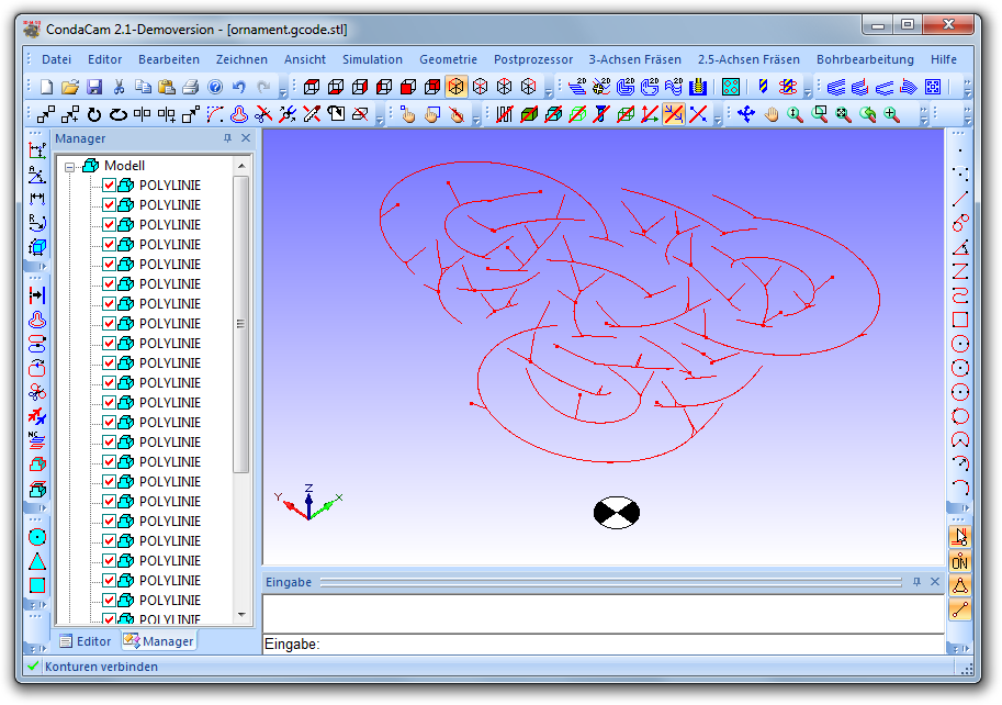
- Export this mesh as STL and import that into CondaCam as a model.
- Extract edges from the model. This generates polylines that include the segments we want at the bottom of the mesh, a parallel copy of them at the top, and also a bunch of unwanted ones parallel to the Z axis.
- Delete the mesh model.
- Select all the polylines and use Zeichnen > Polylinien (erstellen; ändern) > Polylinien erstellen/bearbeiten > Bearbeiten > Auflösen to split them into individual segments.
- Enter right side view (Ansicht > Ansicht > Rechts) and use the rectangular selection tool (Bearbeiten > Fensterauswahl) on the left half of the heap of lines, selecting all the unwanted ones.
- Delete the selected lines so that only the desired ones remain.
- Select all the lines and use Zeichnen > Polylinien (erstellen; ändern) > Polylinien erstellen/bearbeiten > Erstellen to combine them into polylines again.
If you have done a similar thing and know of an easier way, I’d love to hear about it in the comments. It is very well possible that, coming more from a graphics than a CAD background, I am simply missing the obvious.
I also wonder if this would have been easier with RhinoCAM, which is apparently being introduced in the FabLab – having never used Rhino, I am clueless about it.
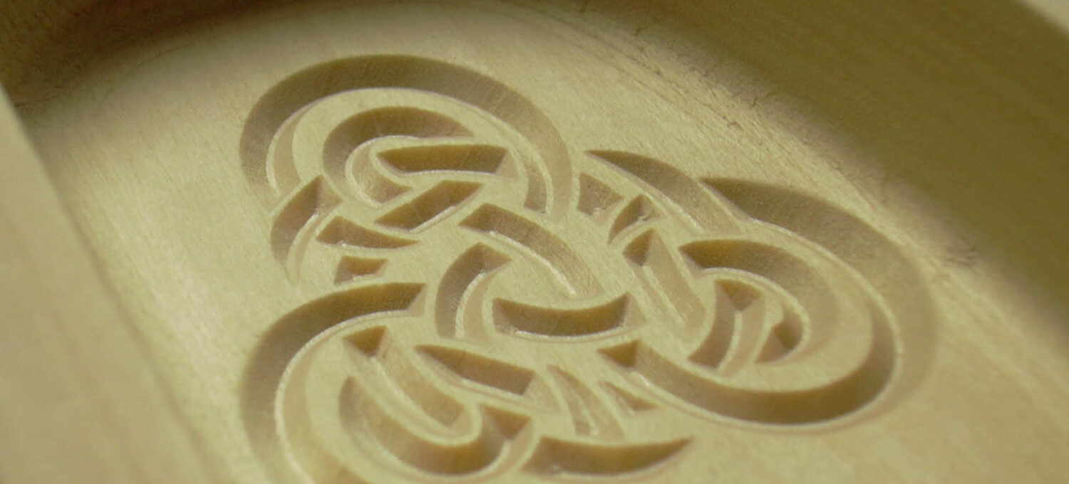
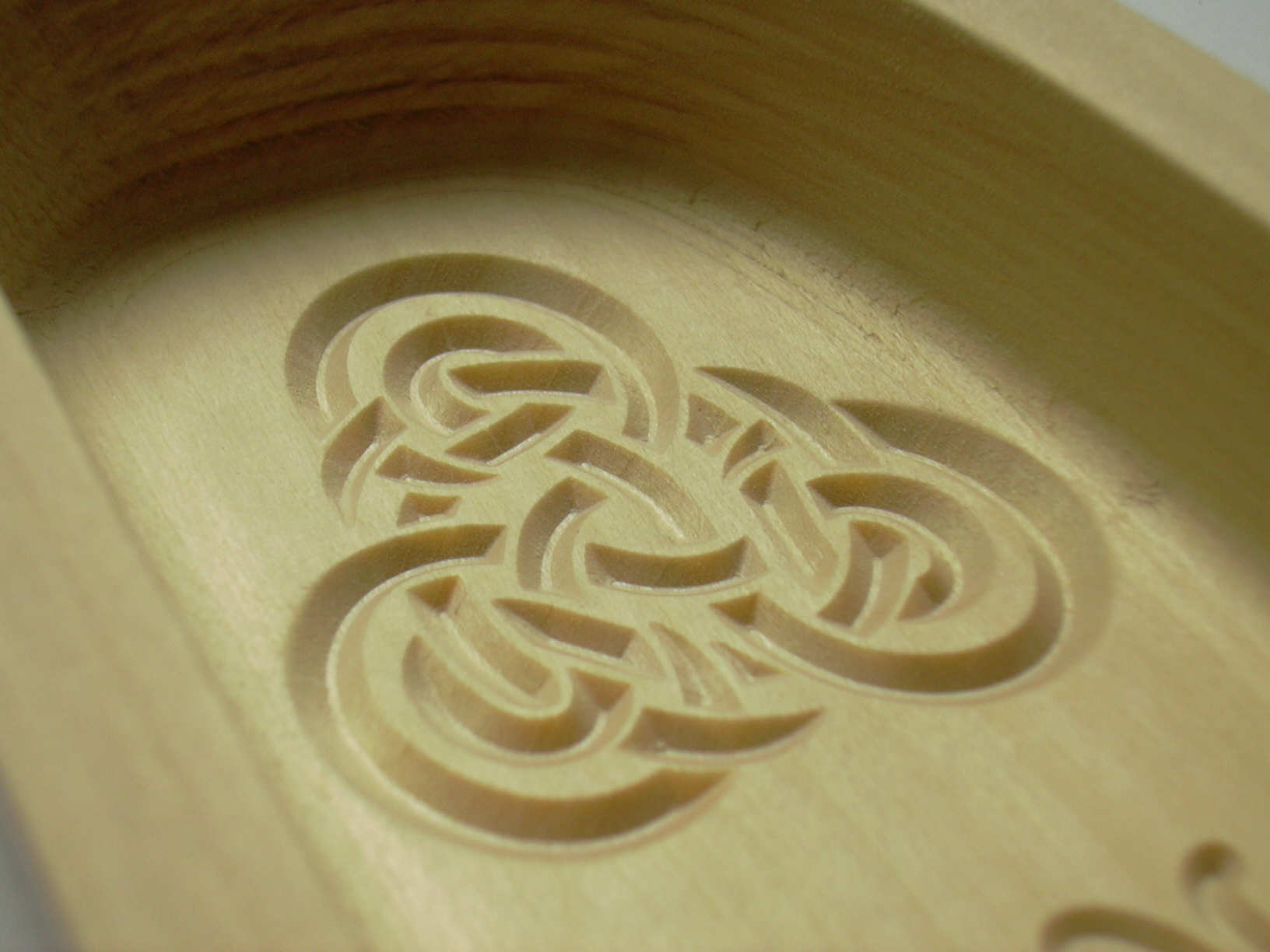
the result looks pretty amazing! but the process to it looks awfully complex and timeconsuming…
have you tried using the bevel option in kontur-fräsen?
i got pretty nice results with my skateboard project…took me no time from scratch to g-code:)
http://zurich.fablab.ch/fab-board
although… i have not tried super tight corners…
Thanks! The process *is* ridiculously complex, but in terms of time (once I found it) it was actually more or less negligible compared to what it took to draw the thing in the first place.
I assume you mean the “Bahnverlauf in Z > Seitenwinkel” option that is available on various 2.5D jobs? Correct me if I’m wrong, but I don’t think this would achieve what I wanted. It does not generate a 3D path, but just modifies the 2D path between one Z plane and the next. That’s fine for features much larger than the bit diameter, such as the beveled edges of your skateboard, but what I was after are features smaller than the bit diameter (and, indeed, sharp corners, only limited by the pointiness of the bit).
I admit though that it didn’t even occur to me to look inside CondaCam for a complete solution without F-Engrave. I just happened upon F-Engrave and thought “hey, this is cool, I want to do something with that”.